Why do this
I have 98 feet of Govee’s RGBICWW outdoor strip (model H70A3) along the eaves. It’s a good strip and the app is fine for leaving the house purple in October. But this year I’m building a mega tree and a yard of pixel props, all sequenced to music in xLights, and the roofline is the biggest thing on the house. Govee’s controller can’t take a frame-by-frame stream from xLights. WLED can.
The usual advice is to cut the Govee connector off and solder on your own. I didn’t want to. The strip is sealed, Govee says it can’t be cut or extended, and I wanted to be able to plug the original controller back in next spring. So the job became: copy Govee’s plug.
Three things had to be figured out, and none of them are published anywhere I could find:
- the mechanical shape of the connector, including its thread
- which of the five pins does what
- what data protocol the strip speaks
The answers are below so you don’t have to repeat it.
What you need
| Part | Qty | Each |
|---|---|---|
| QuinLED An-Penta-Plus What I paid at DrZzs. ESP32 controller with WLED preinstalled. | 1 | $52.00 |
| TE 3-1447221-4 socket contact One per pin. Gold plated, made for 1.0 mm round pins and 20 AWG wire. | 5 | |
| 20 AWG 5-conductor cable, about 6.5 mm jacket Red, black, green, white, yellow if you can get it. It matches Govee's own colours. | 10 ft | |
| Panel-mount DC barrel jack Matched to the plug on Govee's 36 V brick, so the brick plugs in uncut. | 1 | |
| Gasketed plastic junction box, about 260 × 170 × 120 mm inside Roughly what these cost on Amazon. The Wi-Fi antenna works through plastic. | 1 | $23.00 |
| PG9 cable gland For the strip cable. 16 mm hole. | 1 | |
| O-ring, 9.5 mm ID × 1.0 mm Seals the nose against the strip's connector. | 1 | |
| 1/2 in adhesive-lined heat shrink | 2 in | |
| PETG filament | 10 g | |
| Total | about $75.00 |
The strip and its 36 V power brick are the ones you already own. If you’re starting from nothing, Govee’s page for the H70A1/A2/A3 family showed $119.99 when I wrote this.
Why this controller
Most WLED boards are built for 5, 12 or 24 V strips. The H70A3 runs on 36 V. The An-Penta-Plus takes 12 to 48 V in, so Govee’s own power brick runs the controller and the strip together with no converter. It also has the two things this strip needs at once: a level-shifted 5 V data output for the colour pixels, and PWM channels that can drive the warm and cool white LEDs, which Govee wires separately from the colour data. QuinLED calls this its hybrid function, and 36 V strips are on its supported list.
Why 36 V is worth keeping
The voltage is the best thing about this strip. A 5 V or 12 V pixel strip this long needs power injected every few metres, or the far end goes dim and orange. At 36 V the whole 98 feet runs from one end on one small brick. Five wires at the connector, and that’s the entire installation. I didn’t find many other 36 V pixel strips when I went looking.
The price is resolution. Each addressable pixel is a group of nine LEDs, so the whole roofline is 60 pixels. For an outline you see from the street, I’ll take the simple wiring.
The connector
The controller and strip join with a 5-pin keyed plug and a threaded locking collar. The half on the controller’s lead is the one to copy.
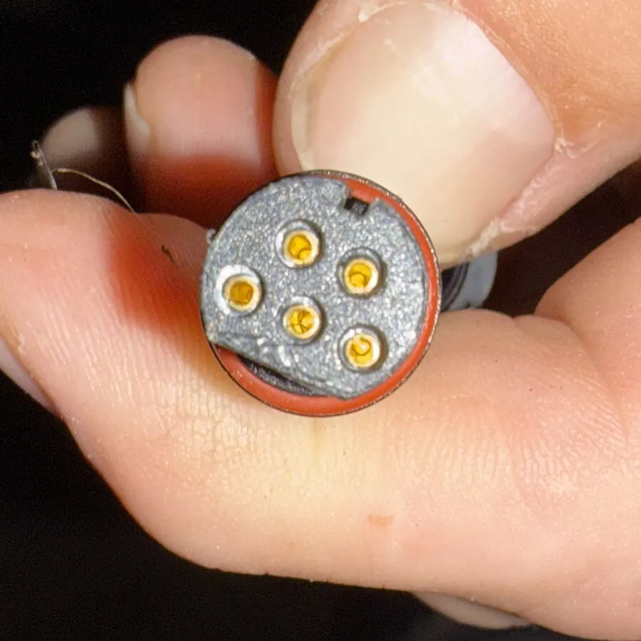
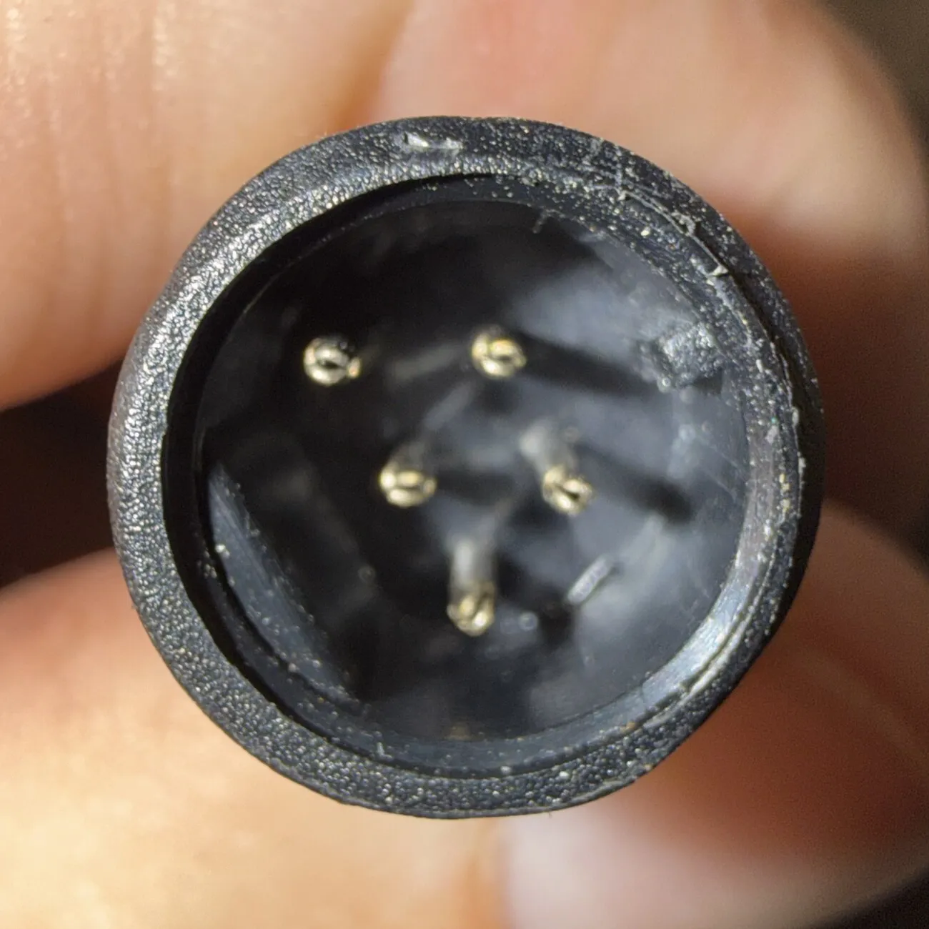
The thread took the longest. I couldn’t measure pitch directly, so I printed a row of test nuts at different pitches and bore sizes. A 1.25 mm nut and a 1.5 mm nut both went on, which can’t both be right. The collar is so short that it only ever engages three turns, and three turns will forgive a near miss. Counting crests gave 7 mm across five gaps, so 1.4 mm, which sits between the two and fits properly. Every dimension I ended up with is a variable at the top of the SCAD file.
Finding the pinout
I started with a multimeter on the controller’s plug and got nowhere useful. With no strip attached, every pin read 36 V against the supply pin, because almost no current flows and the meter can’t tell a switched-off channel from ground.
What worked was opening the controller. It comes apart without a fight, and every pad on the board is labelled in plain English. Thank you, Govee. Whoever signed off on that silkscreen saved me a second evening of guessing.
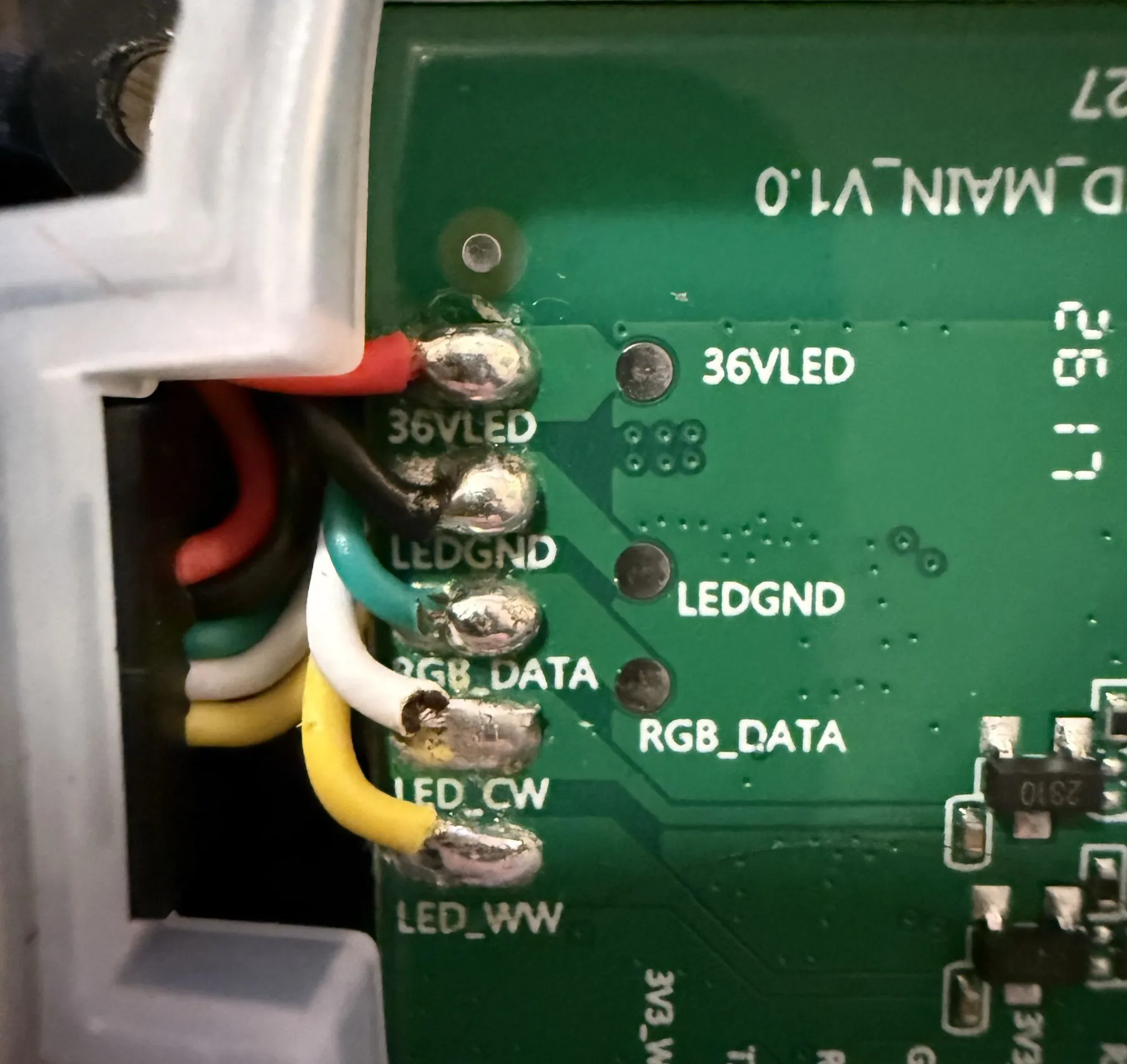
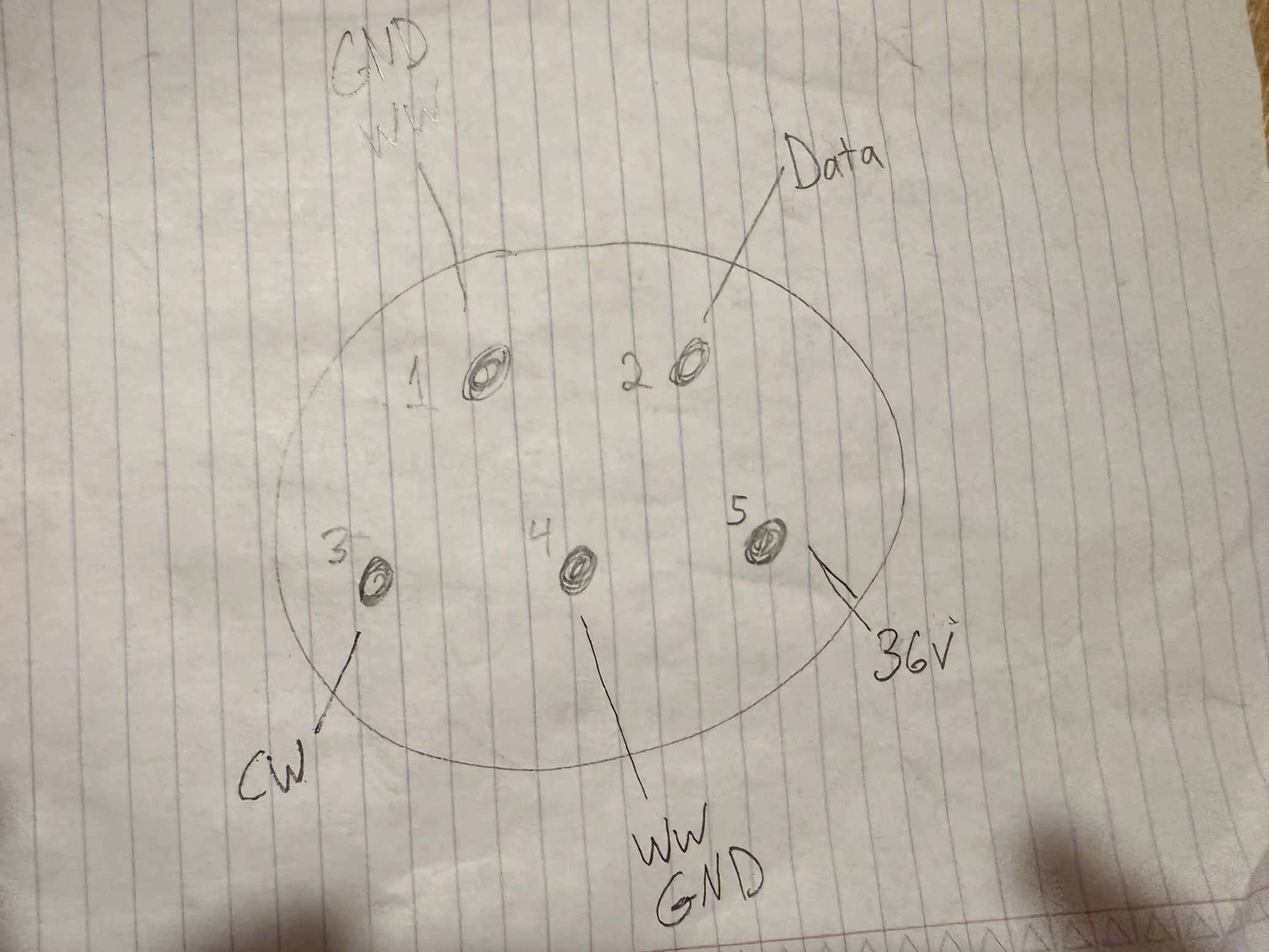
Continuity from each pad to each socket gave the map, with one wrinkle: the beeper said both pin 1 and pin 4 were ground. Switching to the ohms range sorted it out. Pin 1 read 0 Ω to the ground pad. Pin 4 read 0 Ω to the warm white pad and 6 Ω to ground. A beeper triggers on anything under a few tens of ohms, so use the resistance range.
That 6 Ω is odd, by the way. Cool white reads 4.8 MΩ to ground on the same board. I don’t know whether my controller was always like that or whether I hurt it while probing. It doesn’t affect the adapter.
Mating face
looking into the sockets, notch up
Wire side
what you see while inserting terminals
The adapter
The adapter is five printed parts around five metal contacts.
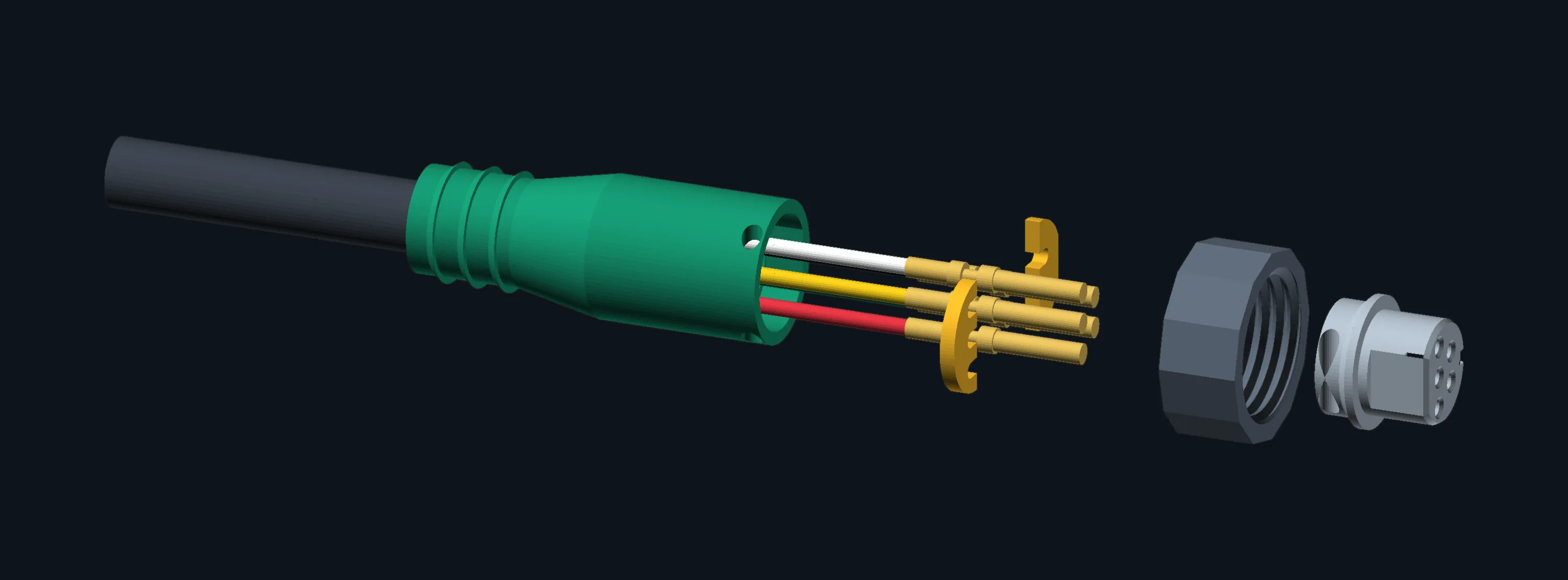
- Cable20 AWG, 5 conductors
- Backshellholds the combs shut, tapers to the cable
- ContactsTE 3-1447221-4, one per wire
- Keeper combsdrop into the neck of each contact
- Collar1.4 mm pitch, spins freely
- Bodykeyed nose, five bores
- Body. The keyed nose with five round bores. Each bore narrows to a 1.5 mm hole at the front so the strip’s pin gets in but the contact can’t push out.
- Collar. Twelve-sided, 12.95 mm bore, 1.4 mm pitch. It slides on from the back and bears on the body’s shoulder, so it spins freely like the original.
- Two combs. Thin plates with U-slots that drop into the narrow neck on each contact. They hold all five contacts in both directions.
- Backshell. Slides over the combs to keep them closed, locks with a short piece of 1.75 mm filament pushed through a side hole, and tapers down to the cable so heat shrink has something to grip.
Choosing the contact
This went through three rounds. A machined Mill-Max receptacle would work but needs soldering in a very small space. Dupont crimp terminals, the kind in every jumper wire kit, do grip the 0.9 mm pins, but they’re made for square header pins, they’re thin tin, and there’s no good way to lock them into a printed part.
The TE 3-1447221-4 is a round socket made for 1.0 mm round pins, gold plated, specified for 20 AWG wire, and it has two collars with a neck between them. That neck is what makes the comb idea work. TE publishes a STEP model, so every dimension in the adapter comes from the real part. I have never been so happy to put my calipers back in the drawer.
Printing
PETG, 0.4 mm nozzle, 0.12 mm layers, no supports. The whole set takes about an hour. The body’s outer walls are only about 0.5 mm thick beside the two outer contacts, so print slowly and check them before you load contacts.
Wiring and assembly
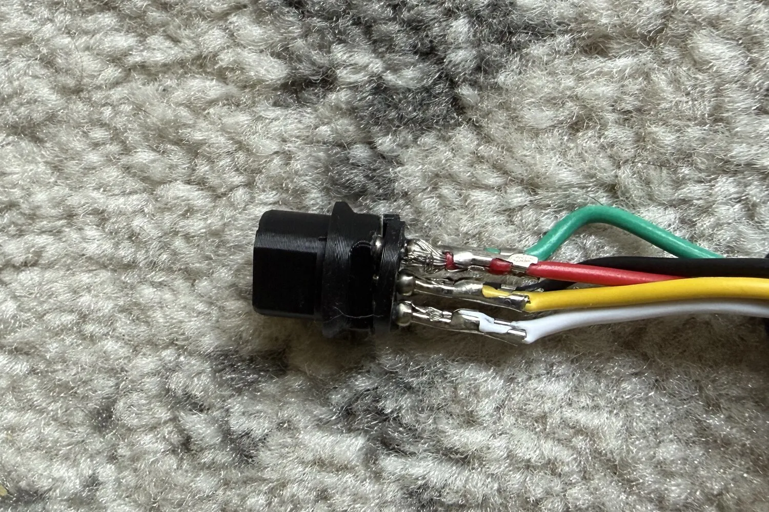
Thread everything onto the cable first
Heat shrink, then the backshell with its narrow end first. Neither will go on after the contacts are crimped.
Strip and crimp
Strip the jacket back about 25 mm and crimp a contact onto each of the five wires. Tug every one.
Load the contacts from the back
Slide the collar onto the body, threads toward the nose. Then push each contact into its bore until it seats. Use the wire-side view in the pin diagram above: red goes bottom left, black goes top right.
Fit the combs and the backshell
Combs in from top and bottom so their slots sit in the contact necks. The comb with two slots goes on the key side. Slide the backshell forward and push the filament pin through.
Prove it with a meter before it touches the strip
Looking into the nose with the notch up, check continuity from each wire’s free end to its socket. Red must land at bottom right and black at top left. Check that no two wires are shorted.
Seal it
Shrink the tube over the backshell tail and the cable. Fit the O-ring before it goes outside.
At the controller
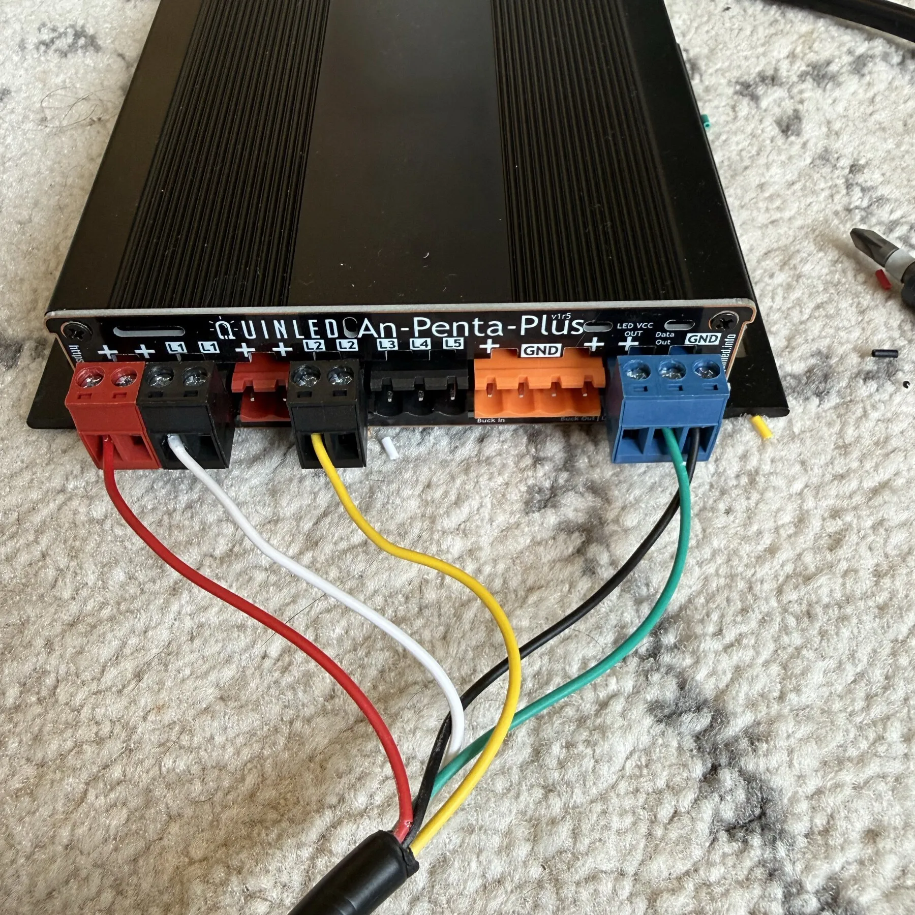
- +red, +36 V
- L1white, cool white
- L2yellow, warm white
- Data Outgreen
- GNDblack
| Wire | Carries | An-Penta-Plus terminal |
|---|---|---|
| Red | +36 V (pin 5) First slot of the red block. Fused on the board. | + |
| White | Cool white (pin 3) | L1 |
| Yellow | Warm white (pin 4) | L2 |
| Green | Data (pin 2) Middle slot of the blue block. | Data Out |
| Black | Ground (pin 1) Blue block. | GND |
Leave LED VCC OUT on the blue block empty, along with the orange buck block and L3 to L5. The strip’s whites are switched on the ground side, the same way the Penta’s PWM channels work, so the white and yellow wires go straight to L1 and L2.
The 36 V brick feeds the Penta’s power input on the other end of the case. I didn’t want to cut Govee’s power lead any more than I wanted to cut the strip, so the box has a panel-mount DC jack and the brick plugs straight into it. The brick tops out at 2 A, so 18 AWG from the jack to the board is plenty. Check polarity with a meter before it goes in.
Setting up WLED
The Penta ships with WLED and QuinLED’s defaults, which were already close. These are the settings saved on mine, running WLED 0.15.0-b7:
| Setting | Value |
|---|---|
| LED type | WS281x |
| Colour order | GRB |
| LED count | 60 |
| Data pin | GPIO 5, the blue 3-pin terminal with VCC left empty |
| Cool white | L1, GPIO 33, analog output |
| Warm white | L2, GPIO 32, analog output |
| White PWM frequency | 600 Hz, lowered from 19,531 Hz. See below. |
The protocol was a guess from other people’s Govee conversions, and it was right first time. To find the length, I sent 50-pixel bands of different colours, noted which colour reached the far end, then repeated with 10-pixel bands. Each addressable pixel drives nine LEDs. The last band ended somewhere in pixels 56 to 60, with a few hidden in the gutter, so I set the count to 60; any extra data just falls off the end. That’s about one pixel every 20 inches. It’s coarse, and it’s fine for a roofline you see from the street.
The white channel problem
Colour works cleanly. White works cleanly. Dimmed white and colour at the same time does not.
When a white channel is dimmed, the controller switches that wire between 0 and 36 V thousands of times a second. The data wire runs beside it in the same cable for the whole run, and those edges swamp the 5 V data signal. What I saw:
| White channel | Colour pixels |
|---|---|
| Off | Clean |
| 100% (no switching) | Clean |
| Dimmed, 19.5 kHz PWM (default) | Frozen on whatever they last showed |
| Dimmed, 600 Hz PWM | Mostly working, with flicker and stray blips |
I’ve left it at 600 Hz. For a show that’s all colour with the whites off, it never comes up. If you want dimmed white mixed with colour, the fix is physical: run data and ground as their own twisted pair outside the 5-core cable, or shorten the run. A small capacitor from data to ground at the adapter might help too. I haven’t tried any of those yet.
How it turned out
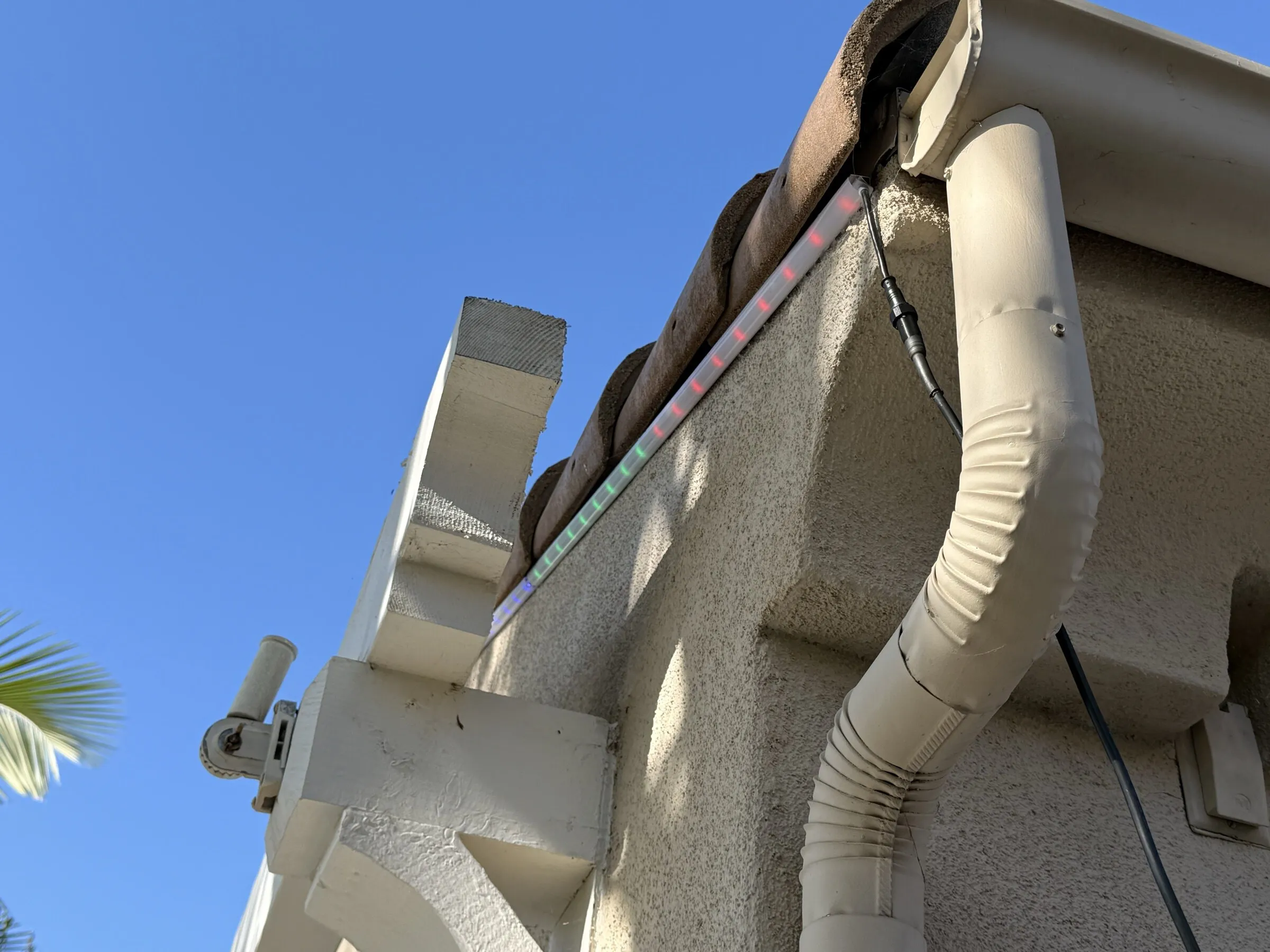
The strip now shows up as an ordinary WLED device. In xLights it’s an Ethernet controller with vendor WLED and protocol DDP, and the roofline is a poly line model with 60 nodes.
What I’d tell you before you start:
- Use Ethernet. My controller’s Wi-Fi signal was around −73 dBm and it was dropping half its packets. The Penta has an Ethernet port. xLights needs a steady stream.
- Give the controller a fixed address in your router so xLights doesn’t lose it after a restart.
- Open the Govee controller first. I spent an evening on voltage readings that the board’s silkscreen answered in a minute.
- Rain-proof, not submersible. Mount the plug pointing down or put a drip loop in the cable.
Sources
- QuinLED: An-Penta-Plus terminals, pinout guide, power handling
- Govee: RGBICWW outdoor strip product page
- Reddit: someone else’s H70A3 extension cables. No files or dimensions were shared, but it’s what gave me the idea.
Files
- 3MFAdapter, all five parts on one plateBody, collar, two keeper combs and the tapered backshell. Sliced for PETG at 0.12 mm.366 KB
- SCADAdapter sourceOpenSCAD. Every dimension in this post is a variable at the top.7 KB
- TEContact drawing and STEP modelThe socket contact the adapter is built around.te.com
Comments
Built one? Got stuck? Found a better way? Say so here. Comments use your GitHub account, and I get a notification for each one.